5 Steps to a 5: AP Physics C - Greg Jacobs 2019
Free-body diagrams and equilibrium
Review the knowledge you need to score high
IN THIS CHAPTER
Summary: Free-body diagrams can help you see forces as vectors, and we’ll review torque as well as a variety of forces: normal force, tension, friction, forces operating on inclined planes, and static and kinetic friction.

Key Ideas
![]() A free-body diagram is a picture that represents an object, along with the forces acting on that object.
A free-body diagram is a picture that represents an object, along with the forces acting on that object.
![]() When the net force on an object equals zero, that object is in equilibrium.
When the net force on an object equals zero, that object is in equilibrium.
![]() The normal force is not always equal to the weight of an object.
The normal force is not always equal to the weight of an object.
![]() Tension is a force applied by a rope or string.
Tension is a force applied by a rope or string.
![]() Friction is only found when there is contact between two surfaces.
Friction is only found when there is contact between two surfaces.
![]() When an object is on an incline, use tilted axes, one parallel to the incline, one perpendicular.
When an object is on an incline, use tilted axes, one parallel to the incline, one perpendicular.
![]() Torque occurs when a force is applied to an object, and that force can cause the object to rotate.
Torque occurs when a force is applied to an object, and that force can cause the object to rotate.
Relevant Equations
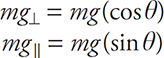
On an inclined plane, the weight vector can be broken into components:
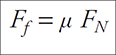
The force of friction is given by
Ff = μFN
Physics, at its essence, is all about simplification. The universe is a complicated place, and if you want to make sense of it—which is what physicists try to do—you need to reduce it to some simplified representation: for example, with free-body diagrams.
We will refer regularly to forces. A force refers to a push or a pull applied to an object. Something can experience many different forces simultaneously—for example, you can push a block forward while friction pulls it backward, but the net force is the vector sum of all of the individual forces acting on the block.
Net Force: The vector sum of all the forces acting on an object
What Is a Free-Body Diagram?
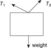
A free-body diagram is a picture that represents one or more objects, along with the forces acting on those objects. The objects are almost always drawn as rectangles or circles, just for the sake of simplicity, and the forces are always shown as vectors. Figure 10.1 shows a few examples.
Free-body diagrams are important because they help us to see forces as vectors. And if you can add vectors, you can analyze a free-body diagram. (If you can’t add vectors, you didn’t read Chapter 9 carefully enough.)
Let’s look at the two examples in Figure 10.1. In the first, a force is directed down. This force, which is the force of gravity, was labeled in the diagram as “weight.” The force of gravity on the hippo (that is, the hippo’s weight) pulls downward. In the second example, a force is directed to the right. The pineapple is being pulled by a rope to the right.
Weight: The force due to gravity, equal to the mass of an object times g, the gravitational field (about 10 N/kg on Earth)
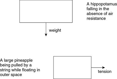
Figure 10.1 Two examples of free-body diagrams. As you see, there is no need to be artistic on the AP exam.
You’ll often see weight abbreviated as mg. Just be careful that the mass you use is in kilograms.
For the rest of this chapter, we focus on objects in equilibrium.
Equilibrium
When the net force on an object equals zero, that object is in equilibrium. At equilibrium, an object is either at rest or moving with a constant velocity, but it is not accelerating.
You’ve heard of Newton’s first law, of course: an object maintains its velocity unless acted upon by a net force. Well, an object in equilibrium is obeying Newton’s first law.
How to Solve Equilibrium Problems

We have a tried-and-true method. Follow it every time you see an equilibrium situation.
1. Draw a proper free-body diagram.
2. Resolve force vectors into x- and y-components, if necessary.
3. Write an expression for the vector sum of the left—right forces. Then write an expression for the vector sum of the up—down forces. Set each of these expressions equal to zero.
4. Solve the resulting algebraic equations.
A Brief Interlude: UNITS!
Before we lose ourselves in the excitement of free-body diagrams, we need to pay tribute to the unit of force: the newton. One N (as newtons are abbreviated) equals one kg·m/s2. We discuss why 1 newton equals 1 kg·m/s2 in a future chapter. For now, let it suffice that any force can be measured in newtons.
A Really Simple Equilibrium Problem
For those of you who prefer to splash your toes in the metaphorical swimming pool of physics before getting all the way in, this section is for you. Look at this situation:
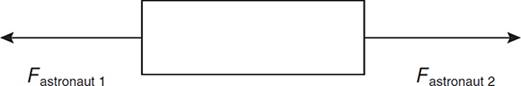
Two astronauts tug on opposite sides of a satellite. The first astronaut tugs to the left with a force of 30 N. With what force does the second astronaut tug in order to keep the satellite at rest?
The solution to this problem is painfully obvious, but we’ll go through the steps just to be thorough.
Step 1: Draw a proper free-body diagram.
We can skip Step 2 because these vectors already line up with each other, so they do not need to be resolved into components.
Step 3: Write expressions for the vector sums.
This problem only involves left—right forces, so we only need one expression. Because we have an equilibrium situation, the net force is ZERO:
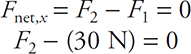
Step 4: Solve.
F2 = 30 N
Very good. Now, let’s see how closely you were paying attention. Here’s the same problem, with a slightly different twist.
Two astronauts tug on opposite sides of a satellite. The first astronaut tugs to the left with a force of 30 N. With what force does the second astronaut tug in order to keep the satellite moving toward him at a constant speed of 20 m/s?
Think for a moment. Does the second astronaut have to apply more, less, or the same force as compared to the previous problem?
The second astronaut applies exactly the same force as in the previous problem! An object moving with constant velocity is in equilibrium, just as if the object were still. This is a central concept in Newtonian mechanics.
Normal Force
Let’s return to Earth for a moment.
In Figure 10.2, a box is sitting on a table. The force of gravity pulls downward (as with the hippo, we’ve labeled this force “weight”). We know from experience that boxes sitting on tables do not accelerate downward; they remain where they are. Some force must oppose the downward pull of gravity.
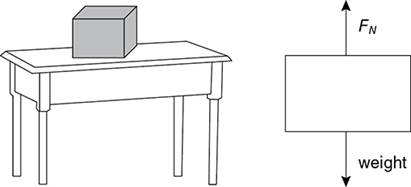
Figure 10.2 Normal force.
This force is called the normal force,1 and it is abbreviated FN. In fact, whenever you push on a hard surface, that surface pushes back on you—it exerts a normal force. So, when you stand on the floor, the floor pushes up on you with the same amount of force with which gravity pulls you down, and, as a result, you don’t fall through the floor.
Normal Force: A force that acts perpendicular to the surface on which an object rests
The normal force is not always equal to the weight of an object! Think about this before we get to the practice problems.
Tension
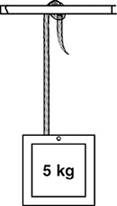
Tension is a force applied by a rope or string. Here are two of our favorite tension problems. The first is super easy, but a good introduction to tension; the second is more involved.
A box has a mass of 5 kg and is hung from the ceiling by a rope. What is the tension in the rope?
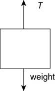
Step 1: Free-body diagram.
Step 2: Vector components.
Hey! These vectors already line up. On to Step 3.
Step 3: Equations.
Remember, weight is equal to mass times the gravitational field, or mg.
Step 4: Solve.
T = 50 N
The same box is now hung by two ropes. One makes a 45-degree angle with the ceiling; the other makes a 30-degree angle with the ceilign. What is the tension in each rope?
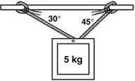
Step 1: Free-body diagram.
Step 2: Vector components.
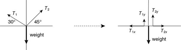
Step 3: Equations.
Let’s start with the x-direction.
![]()
And from vector analysis we know that
![]()
so,

Similarly, if we look at the y-direction,
![]()
and
![]()
so,

Step 4: Solve.
We can solve Equation 1 and Equation 2 simultaneously and find T1 and T2. We’ll let you do this on your own,2 but in case you want to check your answers, T1 = 37 N and T2 = 45 N. (These are reasonable answers, as the tension in each rope is the same power of 10 as the 50 N weight of the box.)
Steps 1, 2, and 3 are the important steps. Step 4 only involves math. “ONLY math?!?” you ask, incredulous. “That’s the toughest part!”
Well, maybe for some people. Getting the actual correct answer does depend on your algebra skills. But, and this is important, this is AP Physics, NOT AP Algebra. The graders of the AP exam will assign most of the credit just for setting up the problem correctly! If you’re stuck on the algebra, skip it! Come up with a reasonable answer for the tensions, and move on!
We’re not kidding. Look at Chapter 7, which discusses approaches to the free-response section, for more about the relative importance of algebra.
Friction
Friction is only found when there is contact between two surfaces.
Friction: A force acting parallel to two surfaces in contact. If an object moves, the friction force always acts opposite the direction of motion.
For example, let’s say you slide a book at a constant speed across a table. The book is in contact with the table, and, assuming your table isn’t frictionless, the table will exert a friction force on the book opposite its direction of motion. Figure 10.3 shows a free-body diagram of that situation.
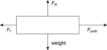
Figure 10.3 Free-body diagram of a book sliding on a table.
We know that because the book represented in Figure 10.3 is not being shoved through the table or flying off it, FN must equal the book’s weight. And because the book moves at constant velocity, the force you exert by pushing the book, Fpush, equals the force of friction, Ff. Remember, being in equilibrium does not necessarily mean that the book is at rest. It could be moving at a constant velocity.
How do we find the magnitude of Ff?
Mu (μ) is the coefficient of friction. This is a dimensionless number (that is, it doesn’t have any units) that describes how big the force of friction is between two objects. It is found experimentally because it differs for every combination of materials (for example, if a wood block slides on a glass surface), but it will usually be given in AP problems that involve friction.
And if μ isn’t given, it is easy enough to solve for—just rearrange the equation for μ algebraically:

Remember, when solving for Ff, do not assume that FN equals the weight of the object in question. Here’s a problem where this reminder comes in handy:
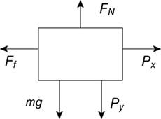
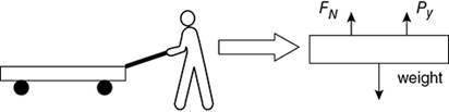
A floor buffer consists of a heavy base (m = 15 kg) attached to a very light handle. A worker pushes the buffer by exerting a force P directly down the length of the handle. If the coefficient of friction between the buffer and the floor is μ = 0.36, what is the magnitude of the force P needed to keep the buffer moving at a constant velocity?
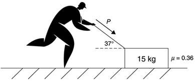
The free-body diagram looks like this:
Exam tip from an AP Physics veteran:
When drawing a free-body diagram, put the tail of the force vectors on the object, with the arrow pointing away from the object. Never draw a force vector pointing into an object, even when something is pushing, as with the P force in this example.
—Chris, high school junior
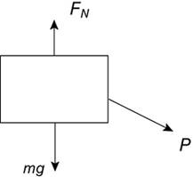
Now, in the vertical direction, there are three forces acting: FN acts up; weight and the vertical component of P act down.
Notice that when we set up the equilibrium equation in the vertical direction, FN - (mg + Py) = 0, we find that FN is greater than mg.
Let’s finish solving this problem together. We’ve already drawn the vertical forces acting on the buffer, so we just need to add the horizontal forces to get a complete free-body diagram with the forces broken up into their components (Steps 1 and 2):
Step 3 calls for us to write equations for the vertical and horizontal directions. We already found the equilibrium equation for the vertical forces,
FN — (mg + Py) = 0,
and it’s easy enough to find the equation for the horizontal forces,
Ff — Px = 0.
To solve this system of equations (Step 4), we can reduce the number of variables with a few substitutions. For example, we can rewrite the equation for the horizontal forces as
μ·FN — P·cos 37° = 0.
Furthermore, we can use the vertical equation to substitute for FN,
FN = mg + P·sin 37°.
Plugging this expression for FN into the rewritten equation for the horizontal forces, and then replacing the variables m, g, and μ with their numerical values, we can solve for P. The answer is P = 93 N.
Static and Kinetic Friction
You may have learned that the coefficient of friction takes two forms: static and kinetic friction. Use the coefficient of static friction if something is stationary, and the coefficient of kinetic friction if the object is moving. The equation for the force of friction is essentially the same in either case: Ff = μFN.
The only strange part about static friction is that the coefficient of static friction is a maximum value. Think about this for a moment … if a book just sits on a table, it doesn’t need any friction to stay in place. But that book won’t slide if you apply a very small horizontal pushing force to it, so static friction can act on the book. To find the maximum coefficient of static friction, find out how much horizontal pushing force will just barely cause the book to move; then use Ff = μFN.
Inclined Planes
These could be the most popular physics problems around. You’ve probably seen way too many of these already in your physics class, so we’ll just give you a few tips on approaching them.
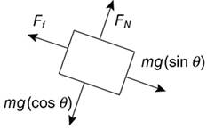
In Figure 10.4 we have a block of mass m resting on a plane elevated an angle θ above the horizontal. The plane is not frictionless. We’ve drawn a free-body diagram of the forces acting on the block in Figure 10.5a.
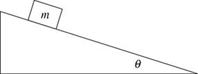
Figure 10.4 Generic inclined-plane situation.
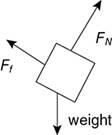
Figure 10.5a Forces acting on the block in Figure 10.4.
Ff is directed parallel to the surface of the plane, and FN is, by definition, directed perpendicular to the plane. It would be a pain to break these two forces into x- and y-components, so instead we will break the “weight” vector into components that “line up” with Ff and FN, as shown in Figure 10.5b.
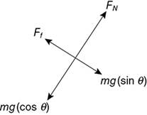
Figure 10.5b Forces acting on the block in Figure 10.4, with the weight vector resolved into components that line up with the friction force and the normal force.
Memorize this

As a rule of thumb, in virtually all inclined-plane problems, you can always break the weight vector into components parallel and perpendicular to the plane, where the component parallel to (pointing down) the plane = mg(sin θ) and the component perpendicular to the plane = mg(cos θ).
This rule always works, as long as the angle of the plane is measured from the horizontal.
Even Physics C Students Must Use Free-Body Diagrams
It must be emphasized that even Physics C students must go through the four-step problem-solving process described in this chapter. Frequently, Physics C students try to take shortcuts, thinking that equilibrium problems are easy, only to miss something important. If free-body diagrams are good enough for professional physicists to use, they are good enough for you.
Torque
Torque occurs when a force is applied to an object, and that force can cause the object to rotate.
Torque = Fd
In other words, the torque exerted on an object equals the force exerted on that object (F) multiplied by the distance between where the force is applied and the fulcrum (d) as long as the force acts perpendicular to the object.
Fulcrum: The point about which an object rotates
Figure 10.6 shows what we mean:
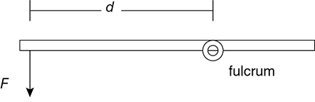
Figure 10.6 The torque applied to this bar equals Fd.
The unit of torque is the newton-meter.
Here’s an example.
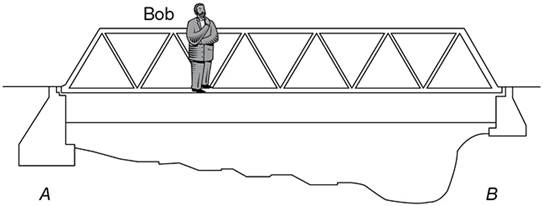
Bob is standing on a bridge. The bridge itself weighs 10,000 N. The span between pillars A and B is 80 m. Bob is 20 m from the center of the bridge. His mass is 100 kg. Assuming that the bridge is in equilibrium, find the force exerted by pillar B on the bridge.
Step 1: Free-body diagram.
We’ll use point A as the fulcrum to start with. Why? In a static equilibrium situation, since the bridge isn’t actually rotating, any point on the bridge could serve as a fulcrum. But we have two unknown forces here, the forces of the supports A and B. We choose the location of one of these supports as the fulcrum, because now that support provides zero torque—the distance from the fulcrum becomes zero! Now all we have to do is solve for the force of support B.
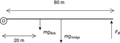
The diagram below isn’t a true “free-body diagram,” because it includes both distance and forces, but it is useful for a torque problem. Bob’s weight acts downward right where he stands.
The bridge’s weight is taken into account with a force vector acting at the bridge’s center of mass; that is, 40 m to the right of pillar A. This is a generally valid approach—replace the weight of an extended object with a single weight vector acting at the center of mass.
Step 2: Vector components.
We don’t have to worry about vector components here. (We would have if the forces had not acted perpendicular to the bridge.)
Step 3: Equations.
Torquenet = counterclockwise - clockwise = 0
(FB)(80 m) — [(100 kg·10 N/kg)(20 m) + (10,000 N)(40 m)] = 0
Step 4: Solve. FB = 5300 N
This is reasonable because pillar B is supporting less than half of the 11,000 N weight of the bridge and Bob. Because Bob is closer to pillar A, and otherwise the bridge is symmetric, A should bear the majority of the weight.
The Physics C exam will often expect you to find the torque provided by a force that acts at an angle. For example, consider a force F acting on a bar at an angle θ, applied a distance x from a pivot. How much torque does this force provide? See Figure 10.7.
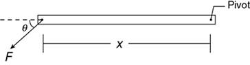
Figure 10.7 Force F acting on a bar at an angle θ.
To solve, break the force vector into horizontal and vertical components, as shown in Figure 10.8.
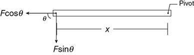
Figure 10.8 Break the force vector into horizontal and vertical components.
The vertical component of F applies a torque of (F sin θ)x. The horizontal component of F does not apply any torque, because it could not cause the bar to rotate. So, the total torque provided by F is (F sin θ)x.
Lever Arm
The “lever arm” for a force is the closest distance from the fulcrum to the line of that force. Then, the torque provided by a force is the force times the lever arm.
Consider Figure 10.9, which represents the same situation as Figure 10.7. Instead of breaking F into components, continue the line of the force. The torque is F times the lever arm shown in the diagram. By trigonometry, you can see that the lever arm is equal to x sin θ. No matter how you look at it, the torque provided by F is still (F sin θ)x.
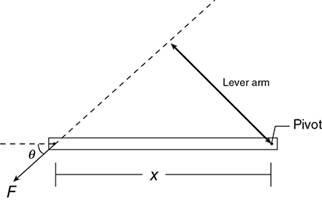
Figure 10.9 Force F acting on a bar at an angle θ
![]() Practice Problems
Practice Problems
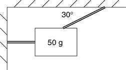
1. A 50-g object is hung by string as shown in the picture above. The left-hand string is horizontal; the angled string measures 30° to the horizontal. What is the tension in the angled string?
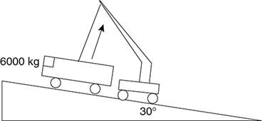
2. A 6000-kg bus sits on a 30° incline. A crane attempts to lift the bus off of the plane. The crane pulls perpendicular to the plane, as shown in the diagram. How much force must the crane apply so that the bus is suspended just above the surface? [cos 30° = 0.87, sin 30° = 0.50]
(A) 52,000 N
(B) 30,000 N
(C) 6000 N
(D) 5200 N
(E) 300 N
3. Give two examples of a situation in which the normal force on an object is less than the object’s weight. Then give an example of a situation in which there is NO normal force on an object.
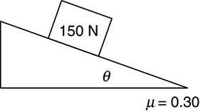
4. A 150-N box sits motionless on an inclined plane, as shown above. What is the angle of the incline?
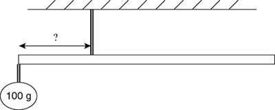
5. A 50-g meterstick is to be suspended by a single string. A 100-g ball hangs from the left-hand edge of the meterstick. Where should the string be attached so that the meterstick hangs in equilibrium?
(A) at the left-hand edge
(B) 40 cm from left-hand edge
(C) 30 cm from right-hand edge
(D) 17 cm from left-hand edge
(E) at the midpoint of the meterstick
![]() Solutions to Practice Problems
Solutions to Practice Problems
1. 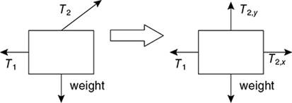
Call the tension in the angled rope T2. In the y-direction, we have T2,y = T2(sin 30 °) acting up, and mg acting down. Set “up” forces equal to “down” forces and solve for tension: T2 = mg/(sin 30°). Don’t forget to use the mass in KILOgrams, i.e., 0.050 kg. The tension thus is (0.050 kg)(10 N/kg)/(0.5) = 1.0 N. This is reasonable because the tension is about the same order of magnitude as the weight of the mass.
2. 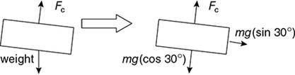
A—Because the force of the crane, Fc, acts perpendicular to the plane, the parallel-to-the-plane direction is irrelevant. So all we need to do is set Fc equal to mg(cos 30°) = (6000 kg)(10 N/kg)(.87) and plug in. Fc = 52,000 N. This is a reasonable answer because it is less than—but on the same order of magnitude as—the weight of the bus.
3. When a block rests on an inclined plane, the normal force on the block is less than the block’s weight, as discussed in the answer to #2. Another example in which the normal force is less than an object’s weight occurs when you pull a toy wagon.
In any situation where an object does not rest on a surface (for example, when something floats in space), there is no normal force.
4. This free-body diagram should be very familiar to you by now.
The box is in equilibrium, so Ff must equal mg (sin θ), and FN must equal mg(cos θ).
μ·FN = μ·mg(cos θ) = mg(sin θ).
Plugging in the values given in the problem we find that μ = 17°. This answer seems reasonable because we’d expect the incline to be fairly shallow.
5. D—This is a torque problem, and the fulcrum is wherever the meterstick is attached to the string. We know that the meterstick’s center of mass is at the 50-cm mark, so we can draw the following picture.
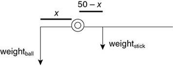
Because the stick is in equilibrium, the clockwise torques equal the counterclockwise torques: (1 N)(x) = (0.5 N)(50 — x). So x = something in the neighborhood of 25/1.5 ~ 17 cm. This answer is less than 50 cm, and is closer to the edge with the heavy mass, so it makes sense.
![]() Rapid Review
Rapid Review
• A free-body diagram is a simplified representation of an object and the forces acting on it.
• When the net force on an object is zero, it is in equilibrium. This means that it is either at rest or that it is moving at a constant velocity.
• To solve an equilibrium problem, draw a good free-body diagram, resolve all forces into x- and y-components, and then set the vector sum of the x-components equal to zero and the vector sum of the y-components equal to zero.
• The units of force are newtons, where 1 N = 1 kg·m/s2.
• Torque equals the force exerted on an object multiplied by the distance between where that force is applied and the fulcrum (the point about which an object can rotate). When an object is in equilibrium, the counterclockwise torques equal the clockwise torques.
• A “normal force” means the force of a solid surface pushing perpendicular to that surface. The normal force is NOT always equal to an object’s weight.
![]()
1When physicists say “normal,” they mean “perpendicular.” The word “normal” in its conventional meaning simply does not apply to physicists.
2Try solving the x-axis equation for T1, then plug that into the y-axis equation:
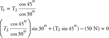
Plug in the value of cos 45°, os 30°, sin 30°, sin 45° … and now it’s easy to solve for T2 = 45 N.