5 Steps to a 5: AP Physics C - Greg Jacobs 2019
Circuits
Review the knowledge you need to score high
IN THIS CHAPTER
Summary: Electric charge flowing through a wire is called current. An electrical circuit is built to control current. In this chapter, you will learn how to predict the effects of current flow.

Key Ideas
![]() The current in series resistors is the same through each, whereas the voltage across series resistors adds to the total voltage.
The current in series resistors is the same through each, whereas the voltage across series resistors adds to the total voltage.
![]() The voltage across parallel resistors is the same across each, whereas the current through parallel resistors adds to the total current.
The voltage across parallel resistors is the same across each, whereas the current through parallel resistors adds to the total current.
![]() The brightness of a light bulb depends on the power dissipated by the bulb.
The brightness of a light bulb depends on the power dissipated by the bulb.
![]() A capacitor blocks current once it has been connected for a while.
A capacitor blocks current once it has been connected for a while.
![]() Physics C students need to know that the time constant of an RC circuit is RC.
Physics C students need to know that the time constant of an RC circuit is RC.
Relevant Equations
Definition of current:

Resistance of a wire in terms of its properties:

Ohm’s law:
V = IR
Power in a circuit:
P = IV
Time constant for an RC circuit:
τ = RC
In the last chapter, we talked about situations where electric charges don’t move around very much. Isolated point charges, for example, just sit there creating an electric field. But what happens when you get a lot of charges all moving together? That, at its essence, is what goes on in a circuit.
Besides discussing circuits in general, this chapter presents a powerful problem-solving technique: the V-I-R chart. As with the chart of variables we used when solving kinematics problems, the V-I-R chart is an incredibly effective way to organize a problem that involves circuits. We hope you’ll find it helpful.
Current
A circuit is simply any path that will allow charge to flow.
Current: The flow of electric charge. In a circuit, the current is the amount of charge passing a given point per unit time.
Technically, a current is defined as the flow of positive charge. We don’t think this makes sense, because electrons—and not protons or positrons—are what flow in a circuit. But physicists have their rationale, and no matter how wacky, we won’t argue with it.
In more mathematical terms, current is defined as follows:

What this means is that the current, I, equals the amount of charge flowing past a certain point divided by the time interval during which you’re making your measurement. This definition tells us that current is measured in coulombs/second. 1 C/s = 1 ampere, abbreviated as 1 A.
Resistance and Ohm’s Law
You’ve probably noticed that just about every circuit drawn in your physics book contains a battery. The reason most circuits contain a battery is because batteries create a potential difference between one end of the circuit and the other. In other words, if you connect the terminals of a battery with a wire, the part of the wire attached to the “+” terminal will have a higher electric potential than the part of the wire attached to the “−” terminal. And positive charge flows from high potential to low potential. So, in order to create a current, you need a battery. (See Figure 19.1.)
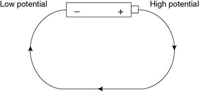
Figure 19.1 Flow of charge in a wire connected to a battery.
In general, the greater the potential difference between the terminals of the battery, the more current flows.
The amount of current that flows in a circuit is also determined by the resistance of the circuit.
Resistance: A property of a circuit that resists the flow of current
Resistance is measured in ohms. 1 ohm is abbreviated as 1 Ω.
If we have some length of wire, then the resistance of that wire can be calculated. Three physical properties of the wire affect its resistance:
• The material the wire is made out of: the resistivity, ρ, of a material is an intrinsic property of that material. Good conducting materials, like gold, have low resistivities.1
• The length of the wire, L: the longer the wire, the more resistance it has.
• The cross-sectional area A of the wire: the wider the wire, the less resistance it has.
We put all of these properties together in the equation for resistance of a wire:

Now, this equation is useful only when you need to calculate the resistance of a wire from scratch. Usually, on the AP exam or in the laboratory, you will be using resistors that have a pre-measured resistance.
Resistor: Something you put in a circuit to change the circuit’s resistance
Resistors are typically ceramic, a material that doesn’t allow current to flow through it very easily. Another common type of resistor is the filament in a light bulb. When current flows into a light bulb, it gets held up in the filament. While it’s hanging out in the filament, it makes the filament extremely hot, and the filament gives off light.
The way that a resistor (or a bunch of resistors) affects the current in a circuit is described by Ohm’s law.
![]()
V is the voltage across the part of the circuit you’re looking at, I is the current flowing through that part of the circuit, and R is the resistance in that part of the circuit. Ohm’s law is the most important equation when it comes to circuits, so make sure you know it well.
When current flows through a resistor, electrical energy is being converted into heat energy. The rate at which this conversion occurs is called the power dissipated by a resistor. This power can be found with the equation

This equation says that the power, P, dissipated in part of a circuit equals the current flowing through that part of the circuit multiplied by the voltage across that part of the circuit.
Using Ohm’s law, it can be easily shown that IV = I2R = V2/R. It’s only worth memorizing the first form of the equation, but any one of these could be useful.
Resistors in Series and in Parallel
In a circuit, resistors can either be arranged in series with one another or parallel to one another. Before we take a look at each type of arrangement, though, we need first to familiarize ourselves with circuit symbols, shown in Figure 19.2.
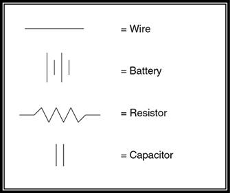
Figure 19.2 Common circuit symbols.
First, let’s examine resistors in series. In this case, all the resistors are connected in a line, one after the other after the other:
To find the equivalent resistance of series resistors, we just add up all the individual resistors.
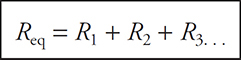
For the circuit in Figure 19.3, Req = 3000 Ω. In other words, using three 1000 Ω resistors in series produces the same total resistance as using one 3000 Ω resistor.
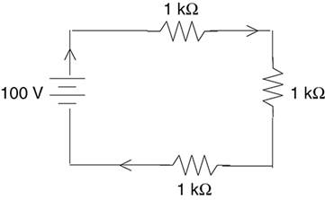
Figure 19.3 Example of series resistors.
Parallel resistors are connected in such a way that you create several paths through which current can flow. For the resistors to be truly in parallel, the current must split, then immediately come back together.
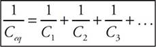
The equivalent resistance of parallel resistors is found by this formula:
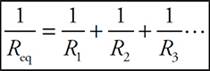
For the circuit in Figure 19.4, the equivalent resistance is 333 Ω. So hooking up three 1000 Ω resistors in parallel produces the same total resistance as using one 333 Ω resistor. (Note that the equivalent resistance of parallel resistors is less than any individual resistor in the parallel combination.)
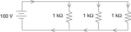
Figure 19.4 Example of parallel resistors.
A Couple of Important Rules
Rule #1—When two resistors are connected in SERIES, the amount of current that flows through one resistor equals the amount of current that flows through the other resistor.
Rule #2—When two resistors are connected in PARALLEL, the voltage across one resistor is the same as the voltage across the other resistor, and is equal to the total voltage across the parallel combination.
The V-I-R Chart
Here it is—the trick that will make solving circuits a breeze. Use this method on your homework. Use this method on your quizzes and tests. But most of all, use this method on the AP exam. It works.
The easiest way to understand the V-I-R chart is to see it in action, so we’ll go through a problem together, filling in the chart at each step along the way.
Find the voltage across each resistor in the circuit shown below.
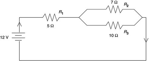
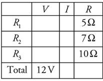
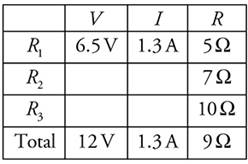
We start by drawing our V-I-R chart, and we fill in the known values. Right now, we know the resistance of each resistor, and we know the total voltage (it’s written next to the battery).
Next, we simplify the circuit. This means that we calculate the equivalent resistance and redraw the circuit accordingly. We’ll first find the equivalent resistance of the parallel part of the circuit:
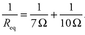
Use your calculator to get 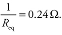
Taking the reciprocal and rounding to 1 significant figure, we get
Req = 4 Ω.
So we can redraw our circuit like this:
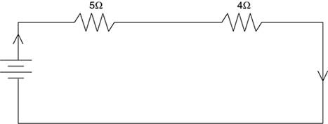
Next, we calculate the equivalent resistance of the entire circuit. Following our rule for resistors in series, we have
Req = 4 Ω + 5 Ω = 9 Ω.
We can now fill this value into the V-I-R chart.
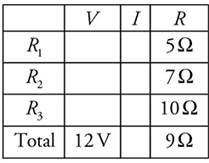
Notice that we now have two of the three values in the “Total” row. Using Ohm’s law, we can calculate the third. That’s the beauty of the V-I-R chart: Ohm’s law is valid whenever two of the three entries in a row are known.
Then we need to put on our thinking caps. We know that all the current that flows through our circuit will also flow through R1 (You may want to take a look back at the original drawing of our circuit to make sure you understand why this is so). Therefore, the I value in the “R1” row will be the same as the I in the “Total” row. We now have two of the three values in the “R1” row, so we can solve for the third using Ohm’s law.
Finally, we know that the voltage across R2 equals the voltage across R3, because these resistors are connected in parallel. The total voltage across the circuit is 12 V, and the voltage across R1 is 6.5 V. So the voltage that occurs between R1 and the end of the circuit is
12 V − 6.5 V = 5.5 V.
Therefore, the voltage across R2, which is the same as the voltage across R3, is 5.5 V. We can fill this value into our table. Finally, we can use Ohm’s law to calculate I for both R2 and R3. The finished V-I-R chart looks like this:
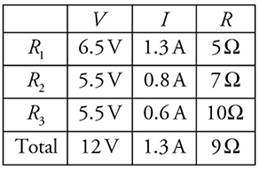
To answer the original question, which asked for the voltage across each resistor, we just read the values straight from the chart.
Now, you might be saying to yourself, “This seems like an awful lot of work to solve a relatively simple problem.” You’re right—it is.
However, there are several advantages to the V-I-R chart. The major advantage is that, by using it, you force yourself to approach every circuit problem exactly the same way. So when you’re under pressure—as you will be during the AP exam—you’ll have a tried-and-true method to turn to.
Also, if there are a whole bunch of resistors, you’ll find that the V-I-R chart is a great way to organize all your calculations. That way, if you want to check your work, it’ll be very easy to do.
Finally, free-response problems that involve circuits generally ask you questions like these.
(a) What is the voltage across each resistor?
(b) What is the current flowing through resistor #4?
(c) What is the power dissipated by resistor #2?
By using the V-I-R chart, you do all your calculations once, and then you have all the values you need to solve any question that the AP writers could possibly throw at you.
Tips for Solving Circuit Problems Using the V-I-R Chart
• First, enter all the given information into your chart. If resistors haven’t already been given names (like “R1”), you should name them for easy reference.
• Next simplify the circuit to calculate Req, if possible.
• Once you have two values in a row, you can calculate the third using Ohm’s law. You CANNOT use Ohm’s law unless you have two of the three values in a row.
• Remember that if two resistors are in series, the current through one of them equals the current through the other. And if two resistors are in parallel, the voltage across one equals the voltage across the other.
Kirchoff’s Laws
Kirchoff’s laws help you solve complicated circuits. They are especially useful if your circuit contains two batteries.
Kirchoff’s laws say:
1. At any junction, the current entering equals the current leaving.
2. The sum of voltages around a closed loop is 0.
The first law is called the “junction rule,” and the second is called the “loop rule.” To illustrate the junction rule, we’ll revisit the circuit from our first problem. (See Figure 19.5.)
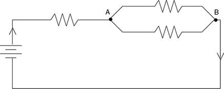
Figure 19.5 Circuit illustrating Kirchoff’s junction rule.
According to the junction rule, whatever current enters Junction “A” must also leave Junction “A.” So let’s say that 1.25 A enters Junction “A,” and then that current gets split between the two branches. If we measured the current in the top branch and the current in the bottom branch, we would find that the total current equals 1.25 A. And, in fact, when the two branches came back together at Junction “B,” we would find that exactly 1.25 A was flowing out through Junction “B” and through the rest of the circuit.
Kirchoff’s junction rule says that charge is conserved: you don’t lose any current when the wire bends or branches. This seems remarkably obvious, but it’s also remarkably essential to solving circuit problems.
Kirchoff’s loop rule is a bit less self-evident, but it’s quite useful in sorting out difficult circuits.
As an example, we’ll show you how to use Kirchoff’s loop rule to find the current through all the resistors in the circuit.
We will follow the steps for using Kirchoff’s loop rule:
• Arbitrarily choose a direction of current. Draw arrows on your circuit to indicate this direction.
• Follow the loop in the direction you chose. When you cross a resistor, the voltage is −IR, where R is the resistance, and I is the current flowing through the resistor. This is just an application of Ohm’s law. (If you have to follow a loop against the current, though, the voltage across a resistor is written +IR.)
• When you cross a battery, if you trace from the − to the + add the voltage of the battery, subtract the battery’s voltage if you trace from + to −.
• Set the sum of your voltages equal to 0. Solve. If the current you calculate is negative, then the direction you chose was wrong—the current actually flows in the direction opposite to your arrows.
In the case of Figures 19.6a and 19.6b, we’ll start by collapsing the two parallel resistors into a single equivalent resistor of 170 Ω. You don’t have to do this, but it makes the mathematics much simpler.
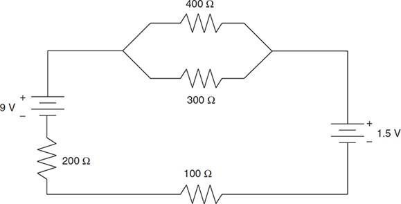
Figure 19.6a Example circuit for using Kirchoff’s loop rule.
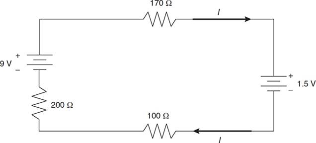
Figure 19.6b Circuit ready for analysis via Kirchoff’s loop rule.
Next, we’ll choose a direction of current flow. But which way? In this particular case, you can probably guess that the 9-V battery will dominate the 1.5-V battery, and thus the current will be clockwise. But even if you aren’t sure, just choose a direction and stick with it—if you get a negative current, you chose the wrong direction.
Here is the circuit redrawn with the parallel resistors collapsed and the assumed direction of current shown. Because there’s now only one path for current to flow through, we have labeled that current I.
Now let’s trace the circuit, starting at the top left corner and working clockwise:
• The 170 Ω resistor contributes a term of −(170 Ω) I.
• The 1.5-V battery contributes the term of −1.5 volts.
• The 100 Ω resistor contributes a term of −(100 Ω) I.
• The 200 Ω resistor contributes a term of −(200 Ω) I.
• The 9-V battery contributes the term of +9 volts.
Combine all the individual terms, and set the result equal to zero. The units of each term are volts, but units are left off below for algebraic clarity:
0 = (−170)I + (−1.5) + (−100)I + (−200)I + (+9).
By solving for I, the current in the circuit is found to be 0.016 A; that is, 16 milliamps, a typical laboratory current.
The problem is not yet completely solved, though—16 milliamps go through the 100 Ω and 200 Ω resistors, but what about the 300 Ω and 400 Ω resistors? We can find that the voltage across the 170 Ω equivalent resistance is (0.016 A)(170 Ω) = 2.7 V. Because the voltage across parallel resistors is the same for each, the current through each is just 2.7 V divided by the resistance of the actual resistor: 2.7 V/300 Ω = 9 mA, and 2.7 V/400 Ω = 7 mA. Problem solved!
Oh, and you might notice that the 9 mA and 7 mA through each of the parallel branches adds to the total of 16 mA—as required by Kirchoff’s junction rule.
Circuits from an Experimental Point of View
When a real circuit is set up in the laboratory, it usually consists of more than just resistors—light bulbs and motors are common devices to hook to a battery, for example. For the purposes of computation, though, we can consider pretty much any electronic device to act like a resistor.
But what if your purpose is not computation? Often on the AP exam, as in the laboratory, you are asked about observational and measurable effects. The most common questions involve the brightness of light bulbs and the measurement (not just computation) of current and voltage.
Brightness of a Bulb
The brightness of a bulb depends solely on the power dissipated by the bulb. (Remember, power is given by any of the equations I2R, IV, or V2/R). You can remember that from your own experience—when you go to the store to buy a light bulb, you don’t ask for a “400-ohm” bulb, but for a “100-watt” bulb. And a 100-watt bulb is brighter than a 25-watt bulb. But be careful—a bulb’s power can change depending on the current and voltage it’s hooked up to. Consider this problem.
A light bulb is rated at 100 W in the United States, where the standard wall outlet voltage is 120 V. If this bulb were plugged in in Europe, where the standard wall outlet voltage is 240 V, which of the following would be true?
(A) The bulb would be one-quarter as bright.
(B) The bulb would be one-half as bright.
(C) The bulb’s brightness would be the same.
(D) The bulb would be twice as bright.
(E) The bulb would be four times as bright.
Your first instinct might be to say that because brightness depends on power, the bulb is exactly as bright. But that’s not right! The power of a bulb can change.
The resistance of a light bulb is a property of the bulb itself, and so will not change no matter what the bulb is hooked to.
Since the resistance of the bulb stays the same while the voltage changes, by V2/R, the power goes up, and the bulb will be brighter. How much brighter? Since the voltage in Europe is doubled, and because voltage is squared in the equation, the power is multiplied by 4—choice E.
Ammeters and Voltmeters
Ammeters measure current, and voltmeters measure voltage. This is pretty obvious, because current is measured in amps, voltage in volts. It is not necessarily obvious, though, how to connect these meters into a circuit.
Remind yourself of the properties of series and parallel resistors—voltage is the same for any resistors in parallel with each other. So if you’re going to measure the voltage across a resistor, you must put the voltmeter in parallel with the resistor. In Figure 19.7, the meter labeled V2 measures the voltage across the 100 Ω resistor, while the meter labeled V1 measures the potential difference between points A and B (which is also the voltage across R1).
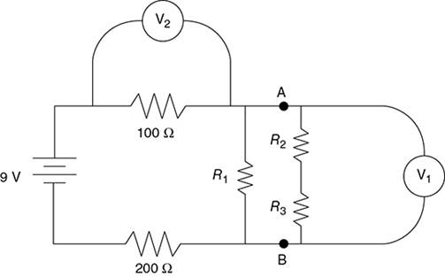
Figure 19.7 Measuring voltage with a voltmeter.
Current is the same for any resistors in series with one another. So, if you’re going to measure the current through a resistor, the ammeter must be in series with that resistor. In Figure 19.8, ammeter A1 measures the current through resistor R1, while ammeter A2 measures the current through resistor R2.
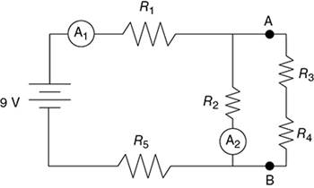
Figure 19.8 Measuring current with an ammeter.
As an exercise, ask yourself, is there a way to figure out the current in the other three resistors based only on the readings in these two ammeters? The answer is in the footnote.2
RC Circuits: Steady-State Behavior
When you have both resistors and capacitors in a circuit, the circuit is called an “RC circuit.” If you remember, we introduced capacitors in Chapter 18, when we talked about charged, parallel plates.
The simplest problems with capacitors in circuits involve “steady-state behavior.” This just means that the circuit has been connected for a while. In these cases, the only thing you’ll generally need to worry about is how to deal with capacitors in series and in parallel.
When capacitors occur in series, you add them inversely. The charge stored on each capacitor in series must be the same.
For the circuit in Figure 19.9, the equivalent capacitance is Ceq = 1.5 μF.
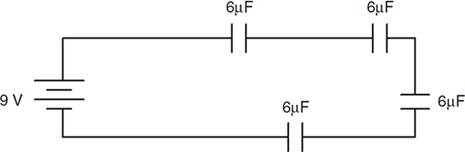
Figure 19.9 Example of capacitors in series.
When capacitors occur in parallel, you add them algebraically. The voltage across each capacitor in parallel must be the same.
The equivalent capacitance for the circuit in Figure 19.10 is 18 μF.
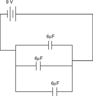
Figure 19.10 Example of capacitors in parallel.
You should also know that the energy stored by a capacitor is
Once the circuit has been connected for a long time, capacitors stop current from flowing. To find the charge stored on or the voltage across a capacitor, just use the equation for capacitors, Q = CV.
For example, imagine that you hook up a 10-V battery to a 5 Ω resistor in series with an uncharged 1 F capacitor. (1 F capacitors are rarely used in actual electronics application—most capacitances are micro- or nanofarads—but they are commonly used for physics class demonstrations!) When the circuit is first hooked up, the capacitor is empty—it is ready and waiting for as much charge as can flow to it. Thus, initially, the circuit behaves as if the capacitor weren’t there. In this case, then, the current through the resistor starts out at 10 V/5 Ω = 2 A.
But, after a long time, the capacitor blocks current. The resistor might as well not be there; we might as well just have a capacitor right across the battery. After a long time, the capacitor takes on the voltage of the battery, 10 V. (So the charge stored on the capacitor is Q = CV = 10 C.)
RC Circuits: Transitional Behavior
Okay, the obvious question here is, “What happens during the in-between times, while the capacitor is charging?” That’s a more complicated question, one that is approached in Physics C. It’s easiest if we start with a discussion of a capacitor discharging. (See Figure 19.11.)
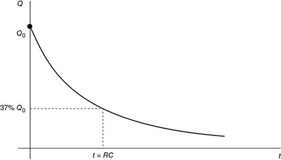
Figure 19.11 Graph of a capacitor discharging.
Consider a circuit with just a resistor R and a capacitor C. (That’s what we mean by an RC circuit.) The capacitor is initially charged with charge Q0. Apply Kirchoff’s voltage rule:
−IR + Vc = 0
where Vc is the voltage across the capacitor, equal to Q/C by the equation for capacitors.
By definition, current is the time derivative of charge,

So substituting this value for I into the Kirchoff equation we wrote above, and rearranging a bit, we get
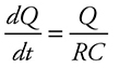
This is a differential equation. On the AP exam you will only rarely have to carry out the algorithmic solution to such an equation; however, you must recognize that the solution will have an exponential term, and you should be able to use limiting case reasoning to guess at the precise form of the solution. See the section on air resistance in Chapter 11 for details.
Here, the charge on the capacitor as a function of time is Q = Q0e−t/RC. What does this mean?
Well, look at the limiting cases. At the beginning of the discharge, when t = 0, the exponential term becomes e0 = 1; so Q = Q0, as expected. After a long time, the exponential term becomes very small (e gets raised to a large negative power), and the charge goes to zero on the capacitor. Of course—that’s what is meant by discharging.
And in between times? Try graphing this on your calculator. You get a function that looks like exponential decay.
What’s cool here is that the product RC has special meaning. The units of RC are seconds: this is a time. RC is called the time constant of the RC circuit. The time constant gives us an idea of how long it will take to charge or discharge a capacitor. (Specifically, after one time constant the capacitor will have 1/e = 37% of its original charge remaining; if the capacitor is charging rather than discharging, it will have charged to 63% of its full capacity.)
So there’s no need to memorize the numerous complicated exponential expressions for charge, voltage, and current in an RC circuit. Just remember that all these quantities vary exponentially, and approach the “after a long time” values asymptotically.
What does the graph of charge vs. time for a charging capacitor look like? (See Figure 19.12.) Think about it a moment. At t = 0, there won’t be any charge on the capacitor, because you haven’t started charging it yet. And after a long time, the capacitor will be fully charged, and you won’t be able to get more charge onto it. So the graph must start at zero and increase asymptotically.
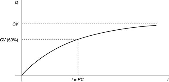
Figure 19.12 Graph of a capacitor charging.
The charge asymptotically approaches the maximum value, which is equal to CV (V is the final voltage across the capacitor). After one time constant, the charge is 1/e = 37% away from its maximum value.
Inductors in Circuits
An inductor makes use of induced EMF (see Chapter 20) to resist changes in current in a circuit. If part of a circuit is coiled, then the magnetic field produced by the coils induces a “back EMF” in the rest of the circuit … that EMF depends on how fast the current is changing, by Faraday’s law. An inductor in a circuit is drawn as a little coil, as shown in Figure 19.13.
![]()
Figure 19.13 Symbol for an inductor in a circuit.
The voltage drop across an inductor is

where L is called the inductance of the inductor. Inductance is measured in units of henrys.
What does this equation mean? If the current is changing rapidly, as when a circuit is first turned on or off, the voltage drop across the inductor is large; if the current is barely changing, as when a circuit has been on for a long time, the inductor’s voltage drop is small.
We can think of an inductor as storing energy in the magnetic field it creates. When current begins to flow through the inductor, it stores up as much energy as it can. After a while, it has stored all the energy it can, so the current just goes through the inductor without trouble. The energy stored in an inductor is found by this equation.
![]()
For the AP Physics C exam, you need to understand circuits with inductors and resistors, as well as circuits with inductors and capacitors.
Other Circuits
RL Circuits
RL circuits contain just an inductor and a resistor, and perhaps a battery, as shown in Figure 19.14.
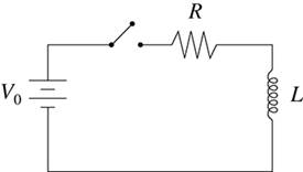
Figure 19.14 An RL circuit.
Imagine that we connect the switch in the circuit in Figure 19.15 at time t = 0. At that point, the current will change rapidly from zero to some nonzero value. So, because ![]() is large, the inductor has a large voltage drop, the resistor has very little voltage drop, and the current cannot immediately reach its maximum value. After a while, though, the current changes less rapidly, the voltage drop across the inductor becomes small, the voltage drop across the resistor gets bigger, and the current in the circuit becomes large.
is large, the inductor has a large voltage drop, the resistor has very little voltage drop, and the current cannot immediately reach its maximum value. After a while, though, the current changes less rapidly, the voltage drop across the inductor becomes small, the voltage drop across the resistor gets bigger, and the current in the circuit becomes large.
A graph of current vs. time for this circuit is shown in Figure 19.15.
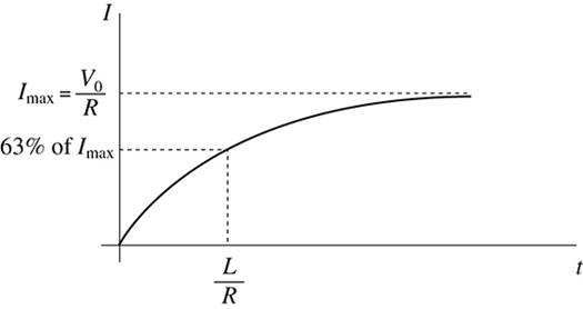
Figure 19.15 Graph of current vs. time for a simple RL circuit.
What would happen if we disconnected the battery? Well, the inductor would discharge its energy through the resistor. At first, the inductor would resist the decrease in current; but after a long time, the current would reach zero, as shown in Figure 19.16.
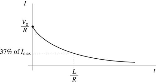
Figure 19.16 Graph of current vs. time for a simple RL circuit once the battery is disconnected.
Note that the current in an RL circuit looks much like that in an RC circuit. In fact, we can define a time constant for an RL circuit, just as we did for the RC circuit, as the time for the current to lose 63% of its value (or to reach 37% of its maximum value when increasing). The time constant for an RL circuit is L/R.
LC Circuits
In a circuit consisting of just a capacitor and an inductor, both the capacitor and inductor try to store energy. They take turns storing the energy in the circuit—the capacitor charges, then discharges, then charges again …
In fact, the charge on the capacitor oscillates from maximum to minimum sinusoidally with period ![]() . You may have to write the solution to a second-order differential equation, just like you did for the mass on a spring in Chapter 17.
. You may have to write the solution to a second-order differential equation, just like you did for the mass on a spring in Chapter 17.
![]() Practice Problems
Practice Problems
Multiple Choice:
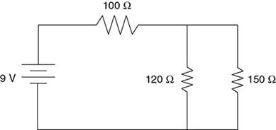
1. A 100 Ω, 120 Ω, and 150 Ω resistor are connected to a 9-V battery in the circuit shown above. Which of the three resistors dissipates the most power?
(A) the 100 Ω resistor
(B) the 120 Ω resistor
(C) the 150 Ω resistor
(D) both the 120 Ω and 150 Ω
(E) all dissipate the same power
2. A 1.0-F capacitor is connected to a 12-V power supply until it is fully charged. The capacitor is then disconnected from the power supply, and used to power a toy car. The average drag force on this car is 2 N. About how far will the car go?
(A) 36 m
(B) 72 m
(C) 144 m
(D) 24 m
(E) 12 m
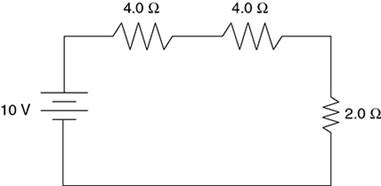
3. Three resistors are connected to a 10-V battery as shown in the diagram above. What is the current through the 2.0 Ω resistor?
(A) 0.25 A
(B) 0.50 A
(C) 1.0 A
(D) 2.0 A
(E) 4.0 A
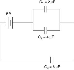
4. Three capacitors are connected as shown in the diagram above. C1 = 2μF; C2 = 4μF; C3 = 6μF. If the battery provides a potential of 9 V, how much charge is stored by this system of capacitors?
(A) 3.0 μC
(B) 30 μC
(C) 2.7 μC
(D) 27 μC
(E) 10 μC
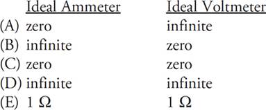
5. What is the resistance of an ideal ammeter and an ideal voltmeter?
Free Response:
6.
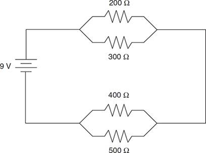
(a) Simplify the above circuit so that it consists of one equivalent resistor and the battery.
(b) What is the total current through this circuit?
(c) Find the voltage across each resistor. Record your answers in the spaces below.
Voltage across 200 Ω resistor: ______
Voltage across 300 Ω resistor: ______
Voltage across 400 Ω resistor: ______
Voltage across 500 Ω resistor: ______
(d) Find the current through each resistor. Record your answers in the spaces below.
Current through 200 Ω resistor: ______
Current through 300 Ω resistor: ______
Current through 400 Ω resistor: ______
Current through 500 Ω resistor: ______
(e) The 500 Ω resistor is now removed from the circuit. State whether the current through the 200 Ω resistor would increase, decrease, or remain the same. Justify your answer.
![]() Solutions to Practice Problems
Solutions to Practice Problems
1. A—On one hand, you could use a V-I-R chart to calculate the voltage or current for each resistor, then use P = IV, I2R, or V2/R to find power. On the other hand, there’s a quick way to reason through this one. Voltage changes across the 100 Ω resistor, then again across the parallel combination. Because the 100 Ω resistor has a bigger resistance than the parallel combination, the voltage across it is larger as well. Now consider each resistor individually. By power = V2/R, the 100 Ω resistor has both the biggest voltage and the smallest resistance, giving it the most power.
2. A—The energy stored by a capacitor is ½CV2. By powering a car, this electrical energy is converted into mechanical work, equal to force times parallel displacement. Solve for displacement, you get 36 m.
3. C—To use Ohm’s law here, simplify the circuit to a 10-V battery with the 10 Ω equivalent resistance. We can use Ohm’s law for the entire circuit to find that 1.0 A is the total current. Because all the resistors are in series, this 1.0 A flows through each resistor, including the 2 Ω resistor.
4. D—First, simplify the circuit to find the equivalent capacitance. The parallel capacitors add to 6 μF. Then the two series capacitors combine to 3 μF. So we end up with 9 V across a 3 μF equivalent capacitance. By the basic equation for capacitors, Q = CV, the charge stored on these capacitors is 27 μC.
5. A—An ammeter is placed in series with other circuit components. In order for the ammeter not to itself resist current and change the total current in the circuit, you want the ammeter to have as little resistance as possible—in the ideal case, zero resistance. But a voltmeter is placed in parallel with other circuit components. If the voltmeter has a low resistance, then current will flow through the voltmeter instead of through the rest of the circuit. Therefore, you want it to have as high a resistance as possible, so the voltmeter won’t affect the circuit being measured.
6. (a) Combine each of the sets of parallel resistors first. You get 120 Ω for the first set, 222 Ω for the second set, as shown in the diagram below. These two equivalent resistances add as series resistors to get a total resistance of 342 Ω.
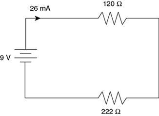
(b) Now that we’ve found the total resistance and we were given the total voltage, just use Ohm’s law to find the total current to be 0.026 A (also known as 26 mA).
(c) and (d) should be solved together using a V-I-R chart. Start by going back one step to when we began to simplify the circuit: a 9-V battery, a 120 Ω combination, and a 222 Ω combination, shown above. The 26-mA current flows through each of these … so use V = IR to get the voltage of each: 3.1 V and 5.8 V, respectively.
Now go back to the original circuit. We know that voltage is the same across parallel resistors. So both the 200 Ω and 300 Ω resistors have a 3.1-V voltage across them. Use Ohm’s law to find that 16 mA goes through the 200Ω resistor, and 10 mA through the 300Ω. Similarly, both the 400Ω and 500 Ω resistors must have 5.8 V across them. We get 15 mA and 12 mA, respectively.
Checking these answers for reasonability: the total voltage adds to 8.9 V, or close enough to 9.0 V with rounding. The current through each set of parallel resistors adds to just about 26 mA, as we expect.
(e) Start by looking at the circuit as a whole. When we remove the 500 Ω resistor, we actually increase the overall resistance of the circuit because we have made it more difficult for current to flow by removing a parallel path. The total voltage of the circuit is provided by the battery, which provides 9.0 V no matter what it’s hooked up to. So by Ohm’s law, if total voltage stays the same while total resistance increases, total current must decrease from 26 mA.
Okay, now look at the first set of parallel resistors. Their equivalent resistance doesn’t change, yet the total current running through them decreases, as discussed above. Therefore, the voltage across each resistor decreases, and the current through each decreases as well.
![]() Rapid Review
Rapid Review
• Current is the flow of positive charge. It is measured in amperes.
• Resistance is a property that impedes the flow of charge. Resistance in a circuit comes from the internal resistance of the wires and from special elements inserted into circuits known as “resistors.”
• Resistance is related to current and voltage by Ohm’s law: V = IR.
• When resistors are connected in series, the total resistance equals the sum of the individual resistances. And the current through one resistor equals the current through any other resistor in series with it.
• When resistors are connected in parallel, the inverse of the total resistance equals the sum of the inverses of the individual resistances. The voltage across one resistor equals the voltage across any other resistor connected parallel to it.
Exam tip from an AP Physics veteran:
Many AP problems test your ability to use Ohm’s law correctly. Ohm’s law cannot be used unless the voltage, current, and resistance all refer to the same circuit element; on a V-I-R chart, this means that Ohm’s law can only be used across a single row of the chart.
—Chat, college junior and physics major
• The V-I-R chart is a convenient way to organize any circuit problem.
• Kirchoff’s junction rule says that any current coming into a junction will leave the junction. This is a statement of conservation of charge. Kirchoff’s loop rule says that the sum of the voltages across a closed loop equals zero. This rule is helpful especially when solving problems with circuits that contain more than one battery.
• Ammeters measure current, and are connected in series; voltmeters measure voltage, and are connected in parallel.
• When capacitors are connected in series, the inverse of the total capacitance equals the sum of the inverses of the individual capacitances. When they are connected in parallel, the total capacitance just equals the sum of the individual capacitances.
• A capacitor’s purpose in a circuit is to store charge. After it has been connected to a circuit for a long time, the capacitor becomes fully charged and prevents the flow of current.
• A capacitor gains or loses charge exponentially. The “time constant” of an RC circuit is equal to the resistance times the capacitance, and gives a characteristic time for the charging or discharging to occur.
• An inductor resists the change of current in a circuit. In an RL circuit, when the battery is first connected, the current increases asymptotically from zero up to a final value of V/R. When the battery is disconnected, the current decreases asymptotically to zero with a time constant of ![]() . In an LC circuit, the charge on the capacitor oscillates from maximum to minimum sinusoidally with period
. In an LC circuit, the charge on the capacitor oscillates from maximum to minimum sinusoidally with period ![]()
![]()
1Resistivity would be given on the AP exam if you need a value. Nothing here to memorize.
2The current through R5 must be the same as through R1, because both resistors carry whatever current came directly from the battery. The current through R3 and R4 can be determined from Kirchoff’s junction rule: subtract the current in R2 from the current in R1, and that’s what’s left over for the right-hand branch of the circuit.